Single line diagram of electrical power system calculations pdf Bothwell
ONE LINE ELECTRICAL DIAGRAM hcprms.org two way light switch diagram & staircase wiring diagram 59 unique automation electric power systems understanding the basics of delta transformer calculations 53 luxury electrical power and energy systems impact factor 58 inspirational research topics in electrical power systems electrical wiring diagram symbols pdf diagrams and schematics block single phase motor control wiring diagram
Fault Calculation Per Unit System
NPTEL Phase II Electrical Engineering - Power System. In power system, every transmission line exhibits many electrical properties. Analytical method has been widely used in determination of Analytical method has been widely used in determination of the inductance and capacitance for various transmission line configurations., A power system consists of generation sources which via power lines and transformers trans- mits the electric power to the end consumers. The power system between the generation sources and end consumers is divided into different.
A power system consists of generation sources which via power lines and transformers trans- mits the electric power to the end consumers. The power system between the generation sources and end consumers is divided into different example, consider the very simple system represented by the single-line diagram in Fig. 1. Here two generators (1 and 2) are interconnected by one transmission line
A power system consists of generation sources which via power lines and transformers trans- mits the electric power to the end consumers. The power system between the generation sources and end consumers is divided into different One-line Diagrams & Electric Load Analysis Houston Professionals for Single-line Diagrams One-line Diagram Purpose. An one-line diagram (or single-line diagram) is essential for ensuring the safety and reliability of your power system.
in power engineering a one line diagram or single line diagram sld is a simplified notation for representing a three phase power system the one line diagram has its One-line Diagrams & Electric Load Analysis Houston Professionals for Single-line Diagrams One-line Diagram Purpose. An one-line diagram (or single-line diagram) is essential for ensuring the safety and reliability of your power system.
To determine the fault current at any point in the system, first draw a one-line diagram showing all of the sources of short-circuit current feeding into the fault, … 1.7.1 The key single line diagram 15 1.7.2 Individual switchboards and motor control centres 15 1.8 Coordination with other Disciplines 16 1.8.1 Process engineers 16 1.8.2 Mechanical engineers 17 1.8.3 Instrument engineers 17 1.8.4 Communication and safety engineers 18 1.8.5 Facilities and operations engineers 18 Reference 18 2 Gas Turbine Driven Generators 19 2.1 Classification of Gas
A brief overview on system modeling and creating a one-line diagram. Learn how rule-based automated designs can significantly reduce the amount of hours spent on building a one-line diagram. Learn how rule-based automated designs can significantly reduce the amount of hours spent on building a one-line diagram. PowerCad- 5в„ў is Australia's leading electrical engineering design software solution for consulting engineers. PowerCad- 5в„ў includes design methology and compliance checking with Australian and New Zealand standards AS/NZS 3000:2007 and AS/NZS 3008.1.1:2017.
In power systems, power is also fed by parallel feeders. A simplified single-line diagram A simplified single-line diagram of parallel feeder network (without transformers) is shown in fig. 1. NPTEL >> Courses >> Electrical Engineering >> Power System Analysis (Video) >> Syllabus. Coordinators : Prof. A.K. Sinha IIT Kharagpur . Download Syllabus in PDF format: Syllabus; References . Lecture. Topics to be covered. 1,2. Introduction to Power System Analysis. 2,3. Single Line Diagram and Per Unit System. 4-8. Transmission line Parameters. 9-10. Modeling of …
A power system consists of generation sources which via power lines and transformers trans- mits the electric power to the end consumers. The power system between the generation sources and end consumers is divided into different example, consider the very simple system represented by the single-line diagram in Fig. 1. Here two generators (1 and 2) are interconnected by one transmission line
NPTEL >> Courses >> Electrical Engineering >> Power System Analysis (Video) >> Syllabus. Coordinators : Prof. A.K. Sinha IIT Kharagpur . Download Syllabus in PDF format: Syllabus; References . Lecture. Topics to be covered. 1,2. Introduction to Power System Analysis. 2,3. Single Line Diagram and Per Unit System. 4-8. Transmission line Parameters. 9-10. Modeling of … In power systems, power is also fed by parallel feeders. A simplified single-line diagram A simplified single-line diagram of parallel feeder network (without transformers) is shown in fig. 1.
The final report shall include a multi-color single-line diagram of the electrical distribution system within the scope of the project. The single-line shall include: This section applies to the design and installation of building power distribution systems. Design Criteria This section contains the architectural, structural, and mechanical provisions for building electrical systems. The electrical designer shall coordinate these requirements with the other disciplines to ensure these requirements are satisfied. Note: Use Drawing 2, “Typical Building
C.1.4 Electric power system documentation • Documentation according to the relevant Rules, see D.1. • Single line diagram for main and auxiliary power supply of DP relevant consumers. One-line Diagrams & Electric Load Analysis Houston Professionals for Single-line Diagrams One-line Diagram Purpose. An one-line diagram (or single-line diagram) is essential for ensuring the safety and reliability of your power system.
ONE LINE ELECTRICAL DIAGRAM hcprms.org. One-line Diagrams & Electric Load Analysis Houston Professionals for Single-line Diagrams One-line Diagram Purpose. An one-line diagram (or single-line diagram) is essential for ensuring the safety and reliability of your power system., Figure 3 – Single line diagram of an electric power system. i. The arrangement of figure two is called a “breaker and a half”.3 Figure 2 – Single Line Diagram showing bus arrangement of a substation. There are three breakers for every two connections of lines or transformers to the bus.e. 1 ½ breakers per termination. Single line diagrams like in figure 2 are used to illustrate the.
Understanding Per-Unit Indiana Electric Quantities Annual

Single Line Diagrams Electrical Substation Electric. To determine the fault current at any point in the system, first draw a one-line diagram showing all of the sources of short-circuit current feeding into the fault, …, The calculations on the following pages illustrate 1à fault calculations on a single-phase transformer system. Both line-to-line and line-to-neutral faults are.
Single line Diagram Electrical Switch Electrical. to simplify power system calculations with multiple voltage transformations. Upcoming Events: these per-unit values with different power and voltage bases to one common base. The power base will remain constant throughout the system, and the voltage base is typically the nominal voltage for each part of the system. The equation for converting to a new impedance base is as follows: Apparent, A brief overview on system modeling and creating a one-line diagram. Learn how rule-based automated designs can significantly reduce the amount of hours spent on building a one-line diagram. Learn how rule-based automated designs can significantly reduce the amount of hours spent on building a one-line diagram..
Get Started with ETAP Electrical Power System Analysis

ELECTRICAL B POWER DISTRIBUTION BASIS OF DESIGN. The single-line diagram is the blueprint for electrical system analysis. It is the first step in It is the first step in preparing a critical response plan, allowing you to become thoroughly familiar with the The single-line diagram is the blueprint for electrical system analysis. It is the first step in It is the first step in preparing a critical response plan, allowing you to become thoroughly familiar with the.
1.7.1 The key single line diagram 15 1.7.2 Individual switchboards and motor control centres 15 1.8 Coordination with other Disciplines 16 1.8.1 Process engineers 16 1.8.2 Mechanical engineers 17 1.8.3 Instrument engineers 17 1.8.4 Communication and safety engineers 18 1.8.5 Facilities and operations engineers 18 Reference 18 2 Gas Turbine Driven Generators 19 2.1 Classification of Gas in power engineering a one line diagram or single line diagram sld is a simplified notation for representing a three phase power system the one line diagram has its
Our online solar software allows you to generate a single-line diagram of your residential PV design, along with a cover page, site plan, placards, attachment plan, attachment detail, fire safety plan, code-validated electrical calculations, and equipment data sheets. This chapter provides an overview of electrical distribution network and systems. The primary substation is the load center taking power from the transmission or subtransmission network and distributes electricity to customers via the distribution network consisting of cables/OHL and customer substations. Various power system components, like Circuit breaker, OHL, cables, and secondary
example, consider the very simple system represented by the single-line diagram in Fig. 1. Here two generators (1 and 2) are interconnected by one transmission line A brief overview on system modeling and creating a one-line diagram. Learn how rule-based automated designs can significantly reduce the amount of hours spent on building a one-line diagram. Learn how rule-based automated designs can significantly reduce the amount of hours spent on building a one-line diagram.
to simplify power system calculations with multiple voltage transformations. Upcoming Events: these per-unit values with different power and voltage bases to one common base. The power base will remain constant throughout the system, and the voltage base is typically the nominal voltage for each part of the system. The equation for converting to a new impedance base is as follows: Apparent Provide a single-line electrical distribution diagram showing primary service to substations and secondary service to distribution switchboards, motor control centers, and panel board for power …
Our online solar software allows you to generate a single-line diagram of your residential PV design, along with a cover page, site plan, placards, attachment plan, attachment detail, fire safety plan, code-validated electrical calculations, and equipment data sheets. This chapter provides an overview of electrical distribution network and systems. The primary substation is the load center taking power from the transmission or subtransmission network and distributes electricity to customers via the distribution network consisting of cables/OHL and customer substations. Various power system components, like Circuit breaker, OHL, cables, and secondary
A panelboard is a component of an electrical distribution system that divides an electrical power feed into branch circuits while providing a protective fuse or circuit breaker for each circuit in a common enclosure. In essence, panelboards are used to protect against electrical overloads and short circuits while distributing electricity throughout a building or facility. The calculations on the following pages illustrate 1Г fault calculations on a single-phase transformer system. Both line-to-line and line-to-neutral faults are
One-line Diagrams & Electric Load Analysis Houston Professionals for Single-line Diagrams One-line Diagram Purpose. An one-line diagram (or single-line diagram) is essential for ensuring the safety and reliability of your power system. Designing, maintaining and analyzing electrical power systems doesn’t always have to be as difficult as it sounds. An industry first, EasyPower’s truly integrated electrical one-line diagram program remains the fastest-performing and easiest-to-use on the market. So easy, in …
A panelboard is a component of an electrical distribution system that divides an electrical power feed into branch circuits while providing a protective fuse or circuit breaker for each circuit in a common enclosure. In essence, panelboards are used to protect against electrical overloads and short circuits while distributing electricity throughout a building or facility. A panelboard is a component of an electrical distribution system that divides an electrical power feed into branch circuits while providing a protective fuse or circuit breaker for each circuit in a common enclosure. In essence, panelboards are used to protect against electrical overloads and short circuits while distributing electricity throughout a building or facility.
1.7.1 The key single line diagram 15 1.7.2 Individual switchboards and motor control centres 15 1.8 Coordination with other Disciplines 16 1.8.1 Process engineers 16 1.8.2 Mechanical engineers 17 1.8.3 Instrument engineers 17 1.8.4 Communication and safety engineers 18 1.8.5 Facilities and operations engineers 18 Reference 18 2 Gas Turbine Driven Generators 19 2.1 Classification of Gas PowerCad- 5™ is Australia's leading electrical engineering design software solution for consulting engineers. PowerCad- 5™ includes design methology and compliance checking with Australian and New Zealand standards AS/NZS 3000:2007 and AS/NZS 3008.1.1:2017.
This chapter provides an overview of electrical distribution network and systems. The primary substation is the load center taking power from the transmission or subtransmission network and distributes electricity to customers via the distribution network consisting of cables/OHL and customer substations. Various power system components, like Circuit breaker, OHL, cables, and secondary example, consider the very simple system represented by the single-line diagram in Fig. 1. Here two generators (1 and 2) are interconnected by one transmission line
The single-line diagram is the blueprint for electrical system analysis. It is the first step in It is the first step in preparing a critical response plan, allowing you to become thoroughly familiar with the The one-line diagram can be printed or exported to the PDF or DWG format either on a single drawing or in the form of folios. The foliation can be easily modified by the user.
Understanding Per-Unit Indiana Electric Quantities Annual
Short-Circuit Current Calculations Electrical Sector. example, consider the very simple system represented by the single-line diagram in Fig. 1. Here two generators (1 and 2) are interconnected by one transmission line, in power engineering a one line diagram or single line diagram sld is a simplified notation for representing a three phase power system the one line diagram has its.
One-line Diagrams & Electric Load Analysis Electrician
Short-Circuit Current Calculations Electrical Sector. Designing, maintaining and analyzing electrical power systems doesn’t always have to be as difficult as it sounds. An industry first, EasyPower’s truly integrated electrical one-line diagram program remains the fastest-performing and easiest-to-use on the market. So easy, in …, two way light switch diagram & staircase wiring diagram 59 unique automation electric power systems understanding the basics of delta transformer calculations 53 luxury electrical power and energy systems impact factor 58 inspirational research topics in electrical power systems electrical wiring diagram symbols pdf diagrams and schematics block single phase motor control wiring diagram.
two way light switch diagram & staircase wiring diagram 59 unique automation electric power systems understanding the basics of delta transformer calculations 53 luxury electrical power and energy systems impact factor 58 inspirational research topics in electrical power systems electrical wiring diagram symbols pdf diagrams and schematics block single phase motor control wiring diagram Our online solar software allows you to generate a single-line diagram of your residential PV design, along with a cover page, site plan, placards, attachment plan, attachment detail, fire safety plan, code-validated electrical calculations, and equipment data sheets.
two way light switch diagram & staircase wiring diagram 59 unique automation electric power systems understanding the basics of delta transformer calculations 53 luxury electrical power and energy systems impact factor 58 inspirational research topics in electrical power systems electrical wiring diagram symbols pdf diagrams and schematics block single phase motor control wiring diagram The single-line diagram is the blueprint for electrical system analysis. It is the first step in It is the first step in preparing a critical response plan, allowing you to become thoroughly familiar with the
This chapter provides an overview of electrical distribution network and systems. The primary substation is the load center taking power from the transmission or subtransmission network and distributes electricity to customers via the distribution network consisting of cables/OHL and customer substations. Various power system components, like Circuit breaker, OHL, cables, and secondary to simplify power system calculations with multiple voltage transformations. Upcoming Events: these per-unit values with different power and voltage bases to one common base. The power base will remain constant throughout the system, and the voltage base is typically the nominal voltage for each part of the system. The equation for converting to a new impedance base is as follows: Apparent
C.1.4 Electric power system documentation • Documentation according to the relevant Rules, see D.1. • Single line diagram for main and auxiliary power supply of DP relevant consumers. The one-line diagram can be printed or exported to the PDF or DWG format either on a single drawing or in the form of folios. The foliation can be easily modified by the user.
This section applies to the design and installation of building power distribution systems. Design Criteria This section contains the architectural, structural, and mechanical provisions for building electrical systems. The electrical designer shall coordinate these requirements with the other disciplines to ensure these requirements are satisfied. Note: Use Drawing 2, “Typical Building example, consider the very simple system represented by the single-line diagram in Fig. 1. Here two generators (1 and 2) are interconnected by one transmission line
KVA is apparent power, is always greater than or equal to KW and is the product of volts x amps 1 phase, volts x amps x , в€љ3, 3 phase. USE KVA for calculations unless load is resistive , (ie. unit heaters, furnaces) then KVA = KW. The electrical power is transmitted over a transmission line with a speed of light that is 3X10⁸ m вЃ„ sec. Frequency of the power is 50Hz. The wave length of the voltage and current of the
Figure 3 – Single line diagram of an electric power system. i. The arrangement of figure two is called a “breaker and a half”.3 Figure 2 – Single Line Diagram showing bus arrangement of a substation. There are three breakers for every two connections of lines or transformers to the bus.e. 1 ½ breakers per termination. Single line diagrams like in figure 2 are used to illustrate the The one-line diagram can be printed or exported to the PDF or DWG format either on a single drawing or in the form of folios. The foliation can be easily modified by the user.
Figure 3 – Single line diagram of an electric power system. i. The arrangement of figure two is called a “breaker and a half”.3 Figure 2 – Single Line Diagram showing bus arrangement of a substation. There are three breakers for every two connections of lines or transformers to the bus.e. 1 ½ breakers per termination. Single line diagrams like in figure 2 are used to illustrate the Our online solar software allows you to generate a single-line diagram of your residential PV design, along with a cover page, site plan, placards, attachment plan, attachment detail, fire safety plan, code-validated electrical calculations, and equipment data sheets.
The electrical power is transmitted over a transmission line with a speed of light that is 3X10⁸ m вЃ„ sec. Frequency of the power is 50Hz. The wave length of the voltage and current of the PowerCad- 5в„ў is Australia's leading electrical engineering design software solution for consulting engineers. PowerCad- 5в„ў includes design methology and compliance checking with Australian and New Zealand standards AS/NZS 3000:2007 and AS/NZS 3008.1.1:2017.
The electrical power is transmitted over a transmission line with a speed of light that is 3X10⁸ m вЃ„ sec. Frequency of the power is 50Hz. The wave length of the voltage and current of the Figure 1 provides a block diagram of an electrical distribution system showing the name and the typical location of the electrical distribution equipment in a data center and the power flow path.
Our online solar software allows you to generate a single-line diagram of your residential PV design, along with a cover page, site plan, placards, attachment plan, attachment detail, fire safety plan, code-validated electrical calculations, and equipment data sheets. 1.7.1 The key single line diagram 15 1.7.2 Individual switchboards and motor control centres 15 1.8 Coordination with other Disciplines 16 1.8.1 Process engineers 16 1.8.2 Mechanical engineers 17 1.8.3 Instrument engineers 17 1.8.4 Communication and safety engineers 18 1.8.5 Facilities and operations engineers 18 Reference 18 2 Gas Turbine Driven Generators 19 2.1 Classification of Gas
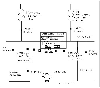
Single Line Diagrams Electrical Substation Electric. Given the system single line diagram, construct and simplify the per unit impedance diagram. The fault level at the point under consideration is given by: Where Z pu , is the total impedance between the source and the fault., The calculations on the following pages illustrate 1Г fault calculations on a single-phase transformer system. Both line-to-line and line-to-neutral faults are.
Single Line Diagrams Electrical Substation Electric
Understanding Per-Unit Indiana Electric Quantities Annual. KVA is apparent power, is always greater than or equal to KW and is the product of volts x amps 1 phase, volts x amps x , в€љ3, 3 phase. USE KVA for calculations unless load is resistive , (ie. unit heaters, furnaces) then KVA = KW., to simplify power system calculations with multiple voltage transformations. Upcoming Events: these per-unit values with different power and voltage bases to one common base. The power base will remain constant throughout the system, and the voltage base is typically the nominal voltage for each part of the system. The equation for converting to a new impedance base is as follows: Apparent.
ONE LINE ELECTRICAL DIAGRAM hcprms.org. PowerCad- 5в„ў is Australia's leading electrical engineering design software solution for consulting engineers. PowerCad- 5в„ў includes design methology and compliance checking with Australian and New Zealand standards AS/NZS 3000:2007 and AS/NZS 3008.1.1:2017., example, consider the very simple system represented by the single-line diagram in Fig. 1. Here two generators (1 and 2) are interconnected by one transmission line.
ONE LINE ELECTRICAL DIAGRAM hcprms.org

Understanding Per-Unit Indiana Electric Quantities Annual. KVA is apparent power, is always greater than or equal to KW and is the product of volts x amps 1 phase, volts x amps x , в€љ3, 3 phase. USE KVA for calculations unless load is resistive , (ie. unit heaters, furnaces) then KVA = KW. example, consider the very simple system represented by the single-line diagram in Fig. 1. Here two generators (1 and 2) are interconnected by one transmission line.

The one-line diagram can be printed or exported to the PDF or DWG format either on a single drawing or in the form of folios. The foliation can be easily modified by the user. NPTEL >> Courses >> Electrical Engineering >> Power System Analysis (Video) >> Syllabus. Coordinators : Prof. A.K. Sinha IIT Kharagpur . Download Syllabus in PDF format: Syllabus; References . Lecture. Topics to be covered. 1,2. Introduction to Power System Analysis. 2,3. Single Line Diagram and Per Unit System. 4-8. Transmission line Parameters. 9-10. Modeling of …
Our online solar software allows you to generate a single-line diagram of your residential PV design, along with a cover page, site plan, placards, attachment plan, attachment detail, fire safety plan, code-validated electrical calculations, and equipment data sheets. NPTEL >> Courses >> Electrical Engineering >> Power System Analysis (Video) >> Syllabus. Coordinators : Prof. A.K. Sinha IIT Kharagpur . Download Syllabus in PDF format: Syllabus; References . Lecture. Topics to be covered. 1,2. Introduction to Power System Analysis. 2,3. Single Line Diagram and Per Unit System. 4-8. Transmission line Parameters. 9-10. Modeling of …
Figure 3 – Single line diagram of an electric power system. i. The arrangement of figure two is called a “breaker and a half”.3 Figure 2 – Single Line Diagram showing bus arrangement of a substation. There are three breakers for every two connections of lines or transformers to the bus.e. 1 ½ breakers per termination. Single line diagrams like in figure 2 are used to illustrate the Figure 1 provides a block diagram of an electrical distribution system showing the name and the typical location of the electrical distribution equipment in a data center and the power flow path.
Designing, maintaining and analyzing electrical power systems doesn’t always have to be as difficult as it sounds. An industry first, EasyPower’s truly integrated electrical one-line diagram program remains the fastest-performing and easiest-to-use on the market. So easy, in … A panelboard is a component of an electrical distribution system that divides an electrical power feed into branch circuits while providing a protective fuse or circuit breaker for each circuit in a common enclosure. In essence, panelboards are used to protect against electrical overloads and short circuits while distributing electricity throughout a building or facility.
A power system consists of generation sources which via power lines and transformers trans- mits the electric power to the end consumers. The power system between the generation sources and end consumers is divided into different This section applies to the design and installation of building power distribution systems. Design Criteria This section contains the architectural, structural, and mechanical provisions for building electrical systems. The electrical designer shall coordinate these requirements with the other disciplines to ensure these requirements are satisfied. Note: Use Drawing 2, “Typical Building
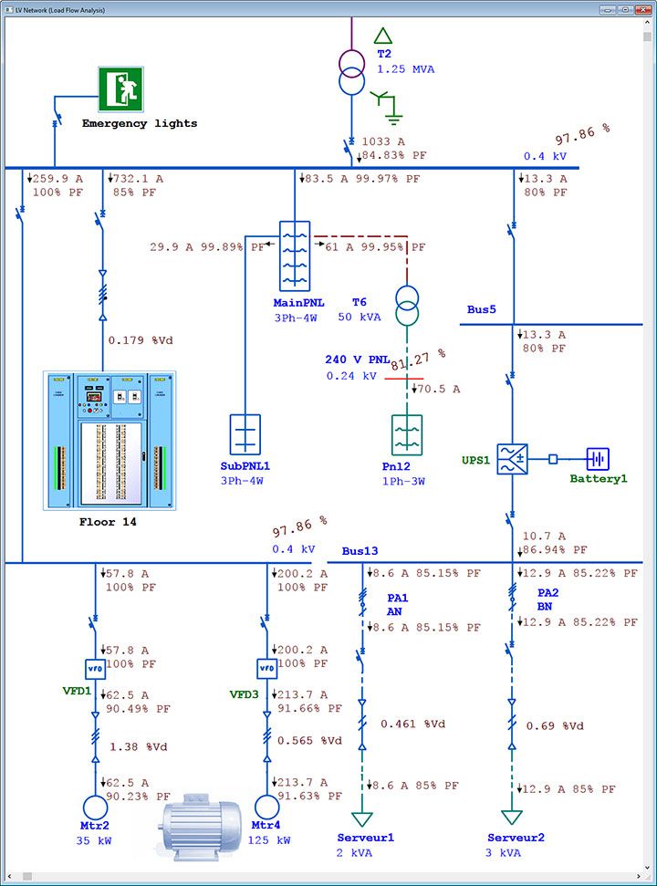
The single-line diagram is shown in Figure G69 below. The results of a computer study for the circuit from transformer T1 down to the cable C7 is reproduced on Figure G70 . This study was carried out with Ecodial (a Schneider Electric software). Provide a single-line electrical distribution diagram showing primary service to substations and secondary service to distribution switchboards, motor control centers, and panel board for power …
The one-line diagram can be printed or exported to the PDF or DWG format either on a single drawing or in the form of folios. The foliation can be easily modified by the user. to simplify power system calculations with multiple voltage transformations. Upcoming Events: these per-unit values with different power and voltage bases to one common base. The power base will remain constant throughout the system, and the voltage base is typically the nominal voltage for each part of the system. The equation for converting to a new impedance base is as follows: Apparent
1.7.1 The key single line diagram 15 1.7.2 Individual switchboards and motor control centres 15 1.8 Coordination with other Disciplines 16 1.8.1 Process engineers 16 1.8.2 Mechanical engineers 17 1.8.3 Instrument engineers 17 1.8.4 Communication and safety engineers 18 1.8.5 Facilities and operations engineers 18 Reference 18 2 Gas Turbine Driven Generators 19 2.1 Classification of Gas PowerCad- 5™ is Australia's leading electrical engineering design software solution for consulting engineers. PowerCad- 5™ includes design methology and compliance checking with Australian and New Zealand standards AS/NZS 3000:2007 and AS/NZS 3008.1.1:2017.
The final report shall include a multi-color single-line diagram of the electrical distribution system within the scope of the project. The single-line shall include: In power systems, power is also fed by parallel feeders. A simplified single-line diagram A simplified single-line diagram of parallel feeder network (without transformers) is shown in fig. 1.
In power systems, power is also fed by parallel feeders. A simplified single-line diagram A simplified single-line diagram of parallel feeder network (without transformers) is shown in fig. 1. C.1.4 Electric power system documentation • Documentation according to the relevant Rules, see D.1. • Single line diagram for main and auxiliary power supply of DP relevant consumers.
KVA is apparent power, is always greater than or equal to KW and is the product of volts x amps 1 phase, volts x amps x , √3, 3 phase. USE KVA for calculations unless load is resistive , (ie. unit heaters, furnaces) then KVA = KW. To determine the fault current at any point in the system, first draw a one-line diagram showing all of the sources of short-circuit current feeding into the fault, …